
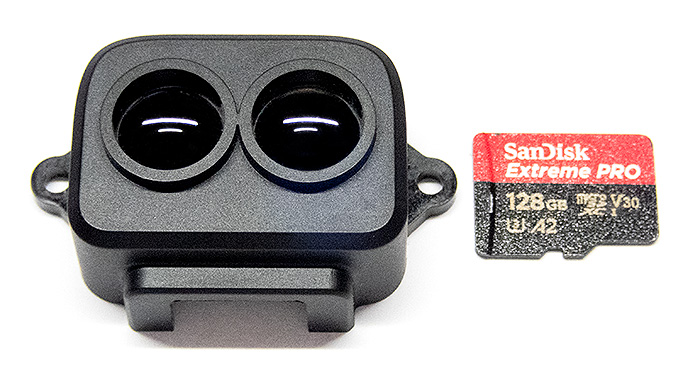
TF-Luna LiDAR Module beside a Micro SD card for scale
A LiDAR (Light Detection and Ranging) system calculates distance by sending out a pulse of light and waiting until it returns after bouncing off an object. This time delay between the light leaving and returning to the sensor is then divided in half and multiplied by the speed of light to determine a real-world distance to that object. This TF-Luna LiDAR Module emits an 850nm infrared beam of light (invisible to the human eye) and can calculate distances from 20cm out to 800cm. This project uses its distance measuring capability to trigger a camera when an object passes through a specific point in space. Unlike Double Break Beam triggers (described HERE), this LiDAR system allows us to place our sensor a good distance from our point of interest and does not require a frame to hold the 4 sensors required to determine a precise point in space.
NOTE:
Due to the time delay between the camera being triggered and it recording an image (due to the relatively slow shutter response times of most cameras), this system may not be useful for recording images of fast-moving objects. Test its effectiveness for your application before deploying the setup.
To achieve faster image captures you could trigger a flash directly and bypass the camera trigger altogether. Unfortunately, this means you would need to have the shutter remain open for a long period of time while waiting for something to trigger an image which will probably increase the background exposure in your image. You could use a low ISO (100), a small lens aperture and record images at night with a black background to help decrease this background exposure. This method could also be used in a dark room with all the lights turned off.
An easy way to connect the trigger directly to a flash is to pick up an inexpensive flash hot shoe adapter with a “sync cord” connector (the small round connector port shown in the image below). All you need to do is strip the two wires in the sync cord and attach them to the camera side of the trigger circuit (shown below). You don’t need a resistor in the flash side of the trigger circuit with this method. The flash is triggered when the two wires are connected, and that's exactly what this trigger circuit does. This system will give much quicker image capture times compared to relying on the in-camera shutter mechanism.
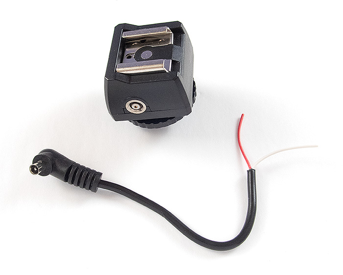
Hot Shoe Adapter with a “Sync Cord” Connector
Camera and Flash Trigger Setup
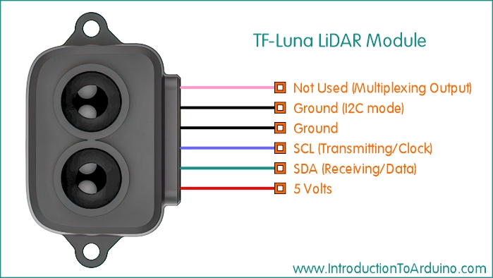
TF-Luna LiDAR Module Wiring Setup
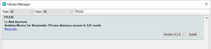
Install the TFLI2C Library to communicate with your TF-Luna LiDAR Module Tools / Manage Libraries / Search for “TFLI2C”
This system would be easy to set up. Once you have your system working properly, choose an area with a high likelihood of finding the creature you want to photograph. Once you have set the Trigger Zone in the code (Minimum and Maximum trigger distances from the LiDAR), set up the LiDAR sensor so the Trigger Zone is free of any other moving objects, and measure the distance from the sensor to the Trigger Zone. Focus your camera on that area by placing an object at that spot and then switch your camera to Manual Focus. Using manual focus is very important because the camera cannot focus quick enough to catch the moving animal (especially at night). If you are recording images with a flash, you can adjust the code to add a delay between images so the flash has enough time to recharge. Record a few test images to make sure you have sharp focus and enough depth of field to record the detail you want. Once you are satisfied with the setup you can let it run as long as you like and look forward viewing your results when you return. The TF-Luna‘s light beam has an illumination angle of approximately 2 degrees so the farther from the sensor the light travels, the wider the beam becomes. At a distance of 100cm the diameter of the light beam will be approximately 3.5cm and at a distance of 800cm (maximum range) the diameter will be approximately 28cm.
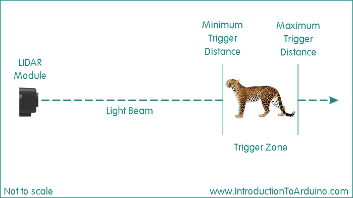
Trigger Zone
Accuracy: ±6cm @ (20cm – 300cm), ±2% @ (300cm – 800cm) (on a flat object with 90% reflectivity) Distance Resolution: 1cm Frame Rate: Default is 100Hz but it can be set to 250Hz Ambient Light Immunity: 70Klux Operating Temperature: -10℃~60℃ Light Wavelength: 850nm Field of View: 2 degrees Supply Voltage: 3.7V - 5.2V Power Consumption: ≤0.35W Dimensions: 35mm X 21.25mm X 12.5mm (L, W, H) Weight: 5g
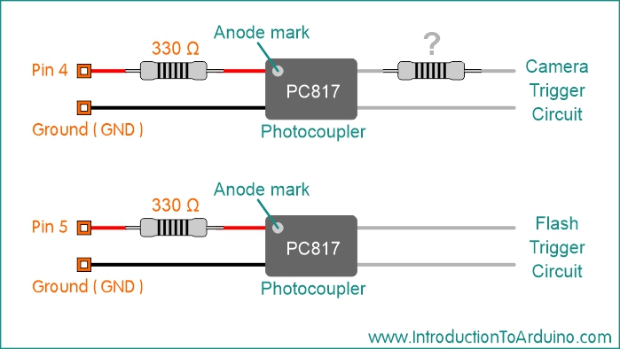
1 Arduino UNO R3 (or similar microcontroller) 1 Cable with a connector to fit your camera (for camera trigger) 1 Additional Resistor (if required for camera trigger setup) 1 PC817 Photocoupler (for camera trigger) 1 330 Ohm Resistor (for camera trigger) 1 Breadboard (for camera trigger) Connector Wires Information about the camera trigger setup can be found HERE
//------------- Code Starts Here ----------------------------

//-----------------------------------------
//Published by IntroductionToArduino.com
//Created by Paul Illsley (www.paulillsley.com)
//Please use and share so others can enjoy
//-----------------------------------------

//======================= Start of Settings ===================

// *** Set the Minimum Distance trigger value (in cm) ***
int Minimum_Distance = 100;

// *** Set the Maximum Distance trigger value (in cm) ***
int Maximum_Distance = 101;

// *** Set the Delay value to wait for the camera's flash to recharge (in seconds) ***
int delay_seconds = 5;

//======================= End of Settings ====================

#include <Arduino.h>
#include <Wire.h>        // Including the Wire library
#include <TFLI2C.h>      // Including the TFLI2C (TFLuna-I2C) Library (this needs to be installed)

TFLI2C tflI2C;

//Defining pin 13 for the Confirmation LED
#define LED 13

// Defining pin 4 for the Camera "Trigger" setup
#define Trigger 4

int16_t  Distance_cm;    // distance in centimeters
int16_t  tfAddr = TFL_DEF_ADR;  // Use this default I2C address

void setup(){
    Serial.begin(115200);  // Initalizing the Serial Port at a baud rate of 115200

    Wire.begin();          // Initalizing the Wire Library

    // setting pin 13 (the LED) as an output (this is also the pin for the UNO's on-board LED).
    pinMode(13,OUTPUT);
    pinMode(4,OUTPUT);

    // Turning pin 4 (Trigger) off
    digitalWrite(Trigger , LOW);
}

void loop(){

    digitalWrite(LED , LOW); // Turning off the LED (Pin 13)

    // Pulling a distance value (in cm) from the TF-Luna
    tflI2C.getData(Distance_cm, tfAddr);

    // Write the distance to the serial monitor
    Serial.print("Distance (cm): ");
    Serial.println(Distance_cm);


    // Checking the distance for "In Trigger Zone"  LED
    // If the distance is above or equal to the Minimum and below or equal to the Maximum
    // turn onn the LED
    if ((Distance_cm >= Minimum_Distance) && (Distance_cm <= Maximum_Distance)){
    digitalWrite(LED , HIGH); // Turning on the LED (Pin 13)
    }
    else{
    digitalWrite(LED , LOW); // Turning off the LED (Pin 13)
    }

    // Checking the distance for Camera Trigger
    // If the distance is above or equal to the Minimum and below or equal to the Maximum
    if ((Distance_cm >= Minimum_Distance) && (Distance_cm <= Maximum_Distance)){

    // Record an image (Trigger)
    digitalWrite(Trigger , HIGH); // Turning on pin 4 (Trigger)
    delay(100); // Delaying 100 milliseconds
    digitalWrite(Trigger , LOW); // Turning off pin 4 (Trigger)

    // Delay a set period of time (delay_seconds) to let the camera's flash recharge
    delay(delay_seconds*1000);
  }
}

//------------- Code Stops Here ----------------------------
Code for Flash and Camera Trigger Setup:
Return to www.introductiontoarduino.com
|